Objectives of Winding
| ||||
| ||||
Most of the textile winding operations deal with the conversion of ringframe bobbins into cones or cheeses. One ringframe bobbin (cop) typically contains around 100 grams of yarn. If the yarn count is 20 tex, then the length of yarn in the package will be around 5 km. As the warping speed in modern machines is around 1000 m/min, direct use of ringframe bobbins in warping will necessitate package change after every 5 minutes. This will reduce the running efficiency of warping machine. Therefore, ringframe bobbins are converted into bigger cones (mass around 2 kgs or more) or cheeses.
| ||||
Ringframe bobbins are also not useable as transverse or weft packages because they have empty core which will require bigger size of the shuttle and thereby causing problem in shedding operations. Therefore, for shuttle looms, pirn winding operations are carried out to manufacture weft packages from cones.
| ||||
Two basic motions are required for effective winding. First, the rotational motion of the package, on which the yarn is being wound, is required. This rotational motion pulls out the yarn from the supply package. Second, the traverse motion is requited so that the entire width of the package is used for winding the yarn. In the absence of the latter, yarns will be wound at the same region by placing one coil over another which is not desirable.
| ||||
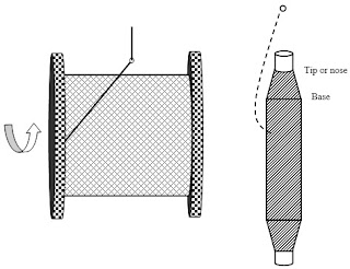
During winding, the yarn can be withdrawn from the supply packages in two ways as depicted in Figure 2.1.
| ||||
| ||||
Figure 2.1: Side withdrawal and over-end withdrawal
| ||||
Side withdrawal is preferable for flanged packages as the yarn does not touch with the flanges. The package has to rotate during the yarn withdrawal. However, for ringframe bobbins, over end withdrawal is performed by keeping the package in almost upright conditions. As one coil comes out from the ringframe bobbin, one twist is either added or subtracted from parent yarn depending on direction of twist in the yarn.
| ||||
Types of Wound Packages
| ||||
There could be three types of wound packages based on the angle at which the yarns are laid on the package.
| ||||
| ||||
Figure 2.2 depicts various types of wound packages.
| ||||
Figure 2.2: Various types of wound packages
| ||||
In parallel wound package, yarns are laid parallel to each other. This helps to maximize the yarn content in the package. However, parallel wound packages suffer from the problem of stability and layers of coils can collapse specially from the two sides of the package. Therefore, double flanged packages are sometimes used for parallel wound packages.
| ||||
Example: Weaver’s beam, warper’s beam
| ||||
In nearly parallel wound package, successive coils of yarn are laid with a very nominal angle. The rate of traverse is very slow in this case.
| ||||
In cross wound package, yarns are laid on the package at considerable angle. As the coils crosses each other very frequently, the package content is lower than that of parallel wound package. However, cross wound package provides very good package stability as the coils often change their direction at the edges of the package.
| ||||
| Example: Cones, Cheeses. | ||||
Important Definitions in Winding
| ||||
| Wind: It is the number of revolutions made by the package (i.e. number of coils wound on the package) during the time taken by the yarn guide to make a traverse in one direction (say from left to right) across the package. | ||||
| Traverse ratio or wind ratio or wind per double traverse: It is the number of revolutions made by the package (i.e. number of coils wound on the package) during the time taken by the yarn guide to make a to and fro traverse. This to and fro traverses of the yarn guide from left to right and back from right to left is known as double traverse. | ||||
| Traverse ratio= 2× Wind | ||||
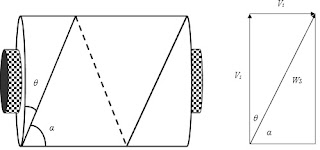
| Angle of wind ( θ ) : It is the a ngle made by the yarn with the sides of the package (Figure 2.3). If surface and traverse speeds are Vs and Vt respectively, then | ||||
| Coil angle ( α ) : It is the a ngle made by the yarn with the axis of the package (Figure 2.3). The coil angle and angle of wind are complementary angles as they add up to 90°. | ||||
Figure 2.3: Angle of wind and coil angle
| ||||
| The net winding speed can be obtained by the resultant vector of surface speed (Vs) and traverse speed (Vt ). | ||||
Winding Machine
| ||||
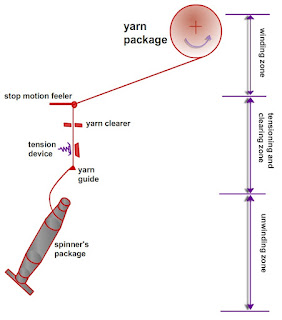
| Figure 2.4 depicts the simplified view of a winding machine. It has three main zones. | ||||
| ||||
Figure 2.4: Zones of winding machine
| ||||
| In the unwinding zone, yarns are unwound from the supply package which is ringframe bobbin in most of the cases. Yarn balloon is formed due to the high speed unwinding of yarn from the supply package. Unwinding tension varies continuously as the winding point shifts from tip to base 0of a ringframe bobbin and vice versa. Besides, the height of the balloon also increases as the supply package becomes empty. | ||||
| In the second zone, tensions are applied on the yarns by using tensioners so that yarns are wound on the package with proper compactness. The objectionable yarn faults as well as other contaminants (coloured and foreign fibres) are also removed by using optical or capacitance based yarn clearer. | ||||
| In the third and final zone, yarns are wound on the package by means of rotational motion of the package and traverse motion of the yarn guide. Based on the operating systems employed in the winding zone, two major winding principles have evolved. |
TEXTILE,YARN MANUFACTURING , FABRIC MANUFACTURING ,TEXTILE TESTING , TEXTILE PROCESSING ,TEXTILE DESIGNING ,GARMENT MANUFACTURING .
WEAVING
Subscribe to:
Post Comments (Atom)


No comments:
Post a Comment